Photography for Compositing – Part V: Calculating Real Defocus in Nuke
- How Much Defocus Is Needed to Match Plate Camera?
Some might say, ‘Why not just use the existing tools? Aren’t there plenty of them on Nukepedia created by professionals who have already done the research and written the formulas for you?’
Well, yes, but I’m one of those guys who can’t help but want to verify the underlying theories myself.
Large studios usually have their own tools developed to achieve realistic depth of field effects, but as someone who only knows how to use the tools, I’m really curious about how those tools are built.
Aside from the tools developed in-house by studios, there are also some impressive toolsets and gizmos provided by experts on Nukepedia, such as OpticalZDefocus and PxF_ZDefocus.
Focusing on ZDefocus, I found that the formulas these tools use to calculate depth of field values are surprisingly in a similar way. However, it still took me some effort to break down and simplify these formulas before I could categorize the results.
This post is just something I worked out during my free time, so take it as you will.
Understand what you need to feed into ZDefocus first
Aside from adjusting parameters based on feeling, if we have all the camera information, we should be able to calculate the ZDefocus values.
But the biggest problem is that even with this information, we still don’t know how does this node calculate behind. What do I need to feed it—what values, what units—so that this node can calculate the degree of defocus for a specific camera, at a specific focal length, with a specific aperture setting, and at a certain distance?
Let’s break down the elements within the ZDefocus node that we’ll be calculating. One of my previous compositing supervisors in Montreal, Mark Joey Tang, created a three-part video series on depth. I’ve selected one which demonstrates how to use depth within the ZDefocus node.
The difference between this article and the video is that this post focuses on determining the optical-correct values for defocus in ZDefocus, rather than discussing Bokeh settings.
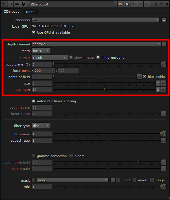
Referring to the image below, within the ZDefocus node, there are five knobs that directly affect the final appearance of depth of field in the image. I’ll also briefly explain why the remaining knobs are not relevant.
- depth channel: To make ZDefocus calculate the depth values, it’s simple: use real distance values. For example, most of the values sampled from
deep.frontare greater than 1, which represents the actual distance from the camera to a point in the scene. - math: The previous point mentioned that depth needs to be in real distance values, but there are still a few types of depth passes. For example, infinity might be represented as either 0 or inf. The math involves defining how the input depth values are converted into distances from the camera. You can check out the examples in Mark’s video for more details.
Those two points are just supplementary information. It’s explained in great detail in Mark’s video, so please make sure to watch the video to understand everything thoroughly.
- focal plane (C): The definition of this attribute is quite straight forward: the absolute value within this attribute is recognized as being in focus.
- maximum: I’ll start with this knob first, as the size knob will take some time to explain. As the name suggests, maximum represents the maximum value. When the value of size exceeds the maximum, the excess will be clamped at the maximum.
- size: I was stuck on this knob for a while because I couldn’t figure out the relationship between the value I put in and the actual defocused bokeh size. However, after reviewing The Foundry’s official explanation, it states: “Sets the size of the blur at infinite depth,” blur is the key word. If we refer back to the official explanation of the size knob in the Blur node, which says: “Sets the radius within which pixels are compared to calculate the blur,” it seems that the value we need to set for the size knob in ZDefocus should also be the blur circle radius calculated based on the camera’s information. I’ve also confirmed this with Xavier, the developer of PxF_ZDefocus, and his formula uses the radius as well. But I still want to double-check this.
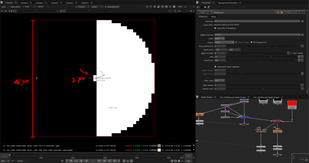
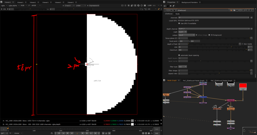
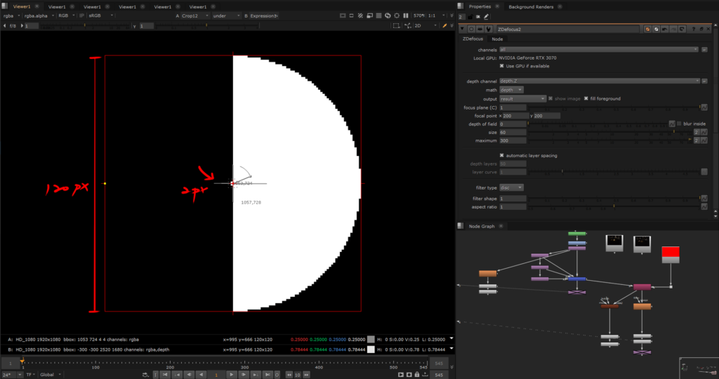
Here are three images to compare the results at different radius values. The only variable is the size attribute in ZDefocus, with all other factors controlled. I’ve used a 2×2 square (which is also circular)
Based on the comparison of values in the images, it seems that the size knob in ZDefocus indeed operates similarly to the size in the Blur node, using the radius to drive the pixel blur range.
When the size is set to 19, the blur circle radius is indeed 19, and the same pattern holds for size values of 29 and 60. Hypothesis verified.
However, one small thing I noticed is that as the defocus level increases, not only does the pixel value decrease, but the expansion of the blur radius does not occur with same incremental increase in size. Instead, there are intervals where the expansion pauses, for example, the blur disk stops expanding at size 5 and starts growing at size 7, and stops at size 57 then starts from size 63. This could suggest that as the pixel value decreases, the blur algorithm might not have enough information to push the pixels outward consistently.
So, why don’t some of the knobs in the red boxes affect the outcome?
Because the focal point knob allows us to sample where the focus is in the scene, and the sampled value shows up in the focal plane field. Therefore, if you already know where the focus is in the scene, you don’t need to manually focus using the focal point.
As for output and depth of field, the formulas we’ll use later will already have calculated the camera’s depth of field. Unless you’re still dissatisfied with the “relatively accurate information” provided, you can adjust the output by tweaking the depth of field settings.
The different settings in the math knob also affect the focal plane and size knobs in ZDefocus.
1. Set math to “direct”, focal plane to 1, size to 1
Documentation of size knob in ZDefocus: “Setting size to 1 allows you to use the values in the depth map as the blur size directly.”
The reason for setting the focal plane to 1 is that, since depth is driving it directly, the focal plane has already been factored into the formula. This approach requires adding a NoOp node as a expression-based node for the camera’s values. You’ll use the formula to create a new depth channel, then Copy it back into the main line to replace the old depth channel. Set math to ‘direct’ and size to 1, which, by definition, tells ZDefocus that the focus point is at the position of the focal plane value, using the new depth values as the defocus blur size.
2. Set math to “depth”, focal plane is filled in according to the camera’s actual focus distance, and the size is filled in after being calculated using the formula.
After testing both ways, the results are quite similar as long as the camera information is consistent.
But where did the formula above come from exactly? Well, let’s break it down below!
So just how much should the background be defocused to match the real camera?
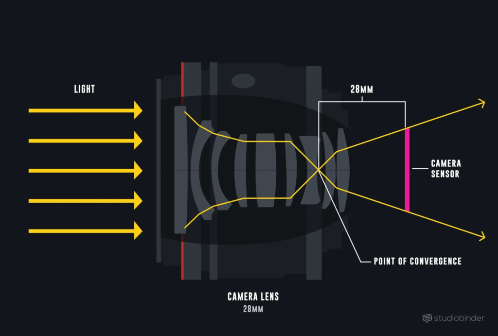
These formulas cannot precisely represent the bokeh size of every camera because we cannot know the exact number of convex and concave lenses inside each lens without disassembling it, nor do we know the refractive index of these lenses.
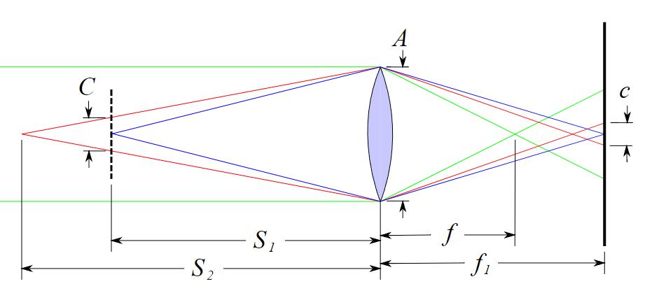
Therefore, what we’re calculating is an approximate value. To simplify the entire process, we assume the lens has only one element, as shown in the diagram below.
A: the diameter of aperture
f: focal length
f₁: the distance between the camera sensor and the aperture
S₁: the distance between the aperture and the focal plane
S₂: The distance between the aperture and a single point on the object
C: the diameter of the blur disk projected onto the focal plane from a single point on the object
c: the diameter of the blur disk projected onto the camera sensor from a single point on the object
Next, let’s follow the steps of the formula provided by Wikipedia. But first, we need to clarify the following two terms to avoid confusion:
Circle of Confusion(CoC): As mentioned in the previous article, this refers to the acceptable level of defocus in an image. The depth of field is composed of CoC of the same size in front of and behind the focus point.
Blur Disk Diameter: This refers to the diameter of the circle from a light source projected onto the image sensor with depth of field. When the blur disk diameter is at the positions of the near and far depth of field, it is equivalent to the circle of confusion diameter.
The formula we mentioned refers to the blur disk diameter.
First, we need to find C, which is the “the diameter of the blur disk projected onto the focal plane from a single point on the object.” Two triangles with the same angles will have the same ratio, C:S2−S1=A:S2C : S_2 – S_1 = A : S_2C:S2−S1=A:S2.
Thus, we will get:

To reduce the parameters and simplify the formula above, we derive three additional simple lens formulas based on the Wikipedia diagram. These are standard formulas that can be found by searching ‘lens equations’ on Google, refined through research and simplification.
- the diameter of the blur disk projected onto the camera sensor from a single point on the object(c) = the diameter of the blur disk projected onto the focal plane from a single point on the object(C) * magnification(m)

- magnification(m) = the distance between the camera sensor and the aperture(f₁) / the distance between the aperture and the focal plane(S₁)

- 1/focal length(f) = 1/the distance between the camera sensor and the aperture(f₁) + 1/the distance between the aperture and the focal plane(S₁)

- f stop(N) = focal length(f) / aperture(A)
D means “Diameter of Entrance Pupil”, but it equals to the diameter of aperture in this case, D=A.

After a series of substitutions and simplifications, the final result will be the final result.

If we want to find the blur disk diameter at infinity with a finite focus distance, S2−S1 will be equivalent to S2, and we will have this formula:

Alright, we have calculated the blur disk diameter on the sensor, but this is not the final value to input into ZDefocus. We still need to convert this into pixels based on the sensor size and resolution ratio. According to the definition of the size knob in ZDefocus, we divide by 2 to convert the diameter into radius, as shown in the diagram below:
The relationship between the sensor size and resolution is just a ratio. In the formula, it can be based on the width ratio, the height ratio, or the diagonal ratio. The result will be the same.
Let's take a look in Nuke using lens formula
Let’s look at an actual example, setting math to direct for the examples below.
The first set of tests used a Nikon 750D with a Nikkor 24-70 mm f/2.8.
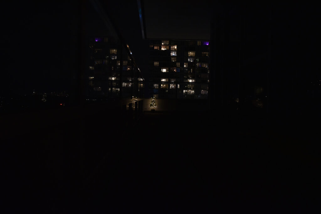
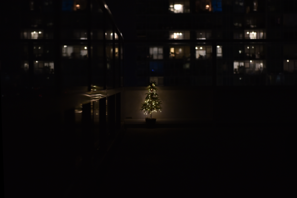
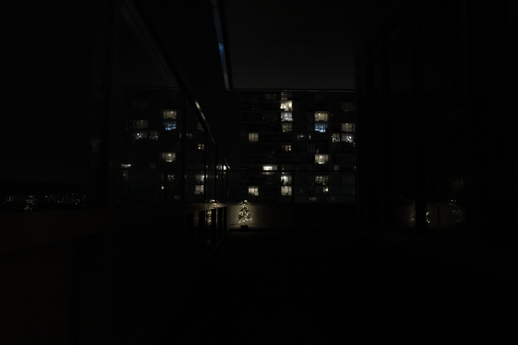
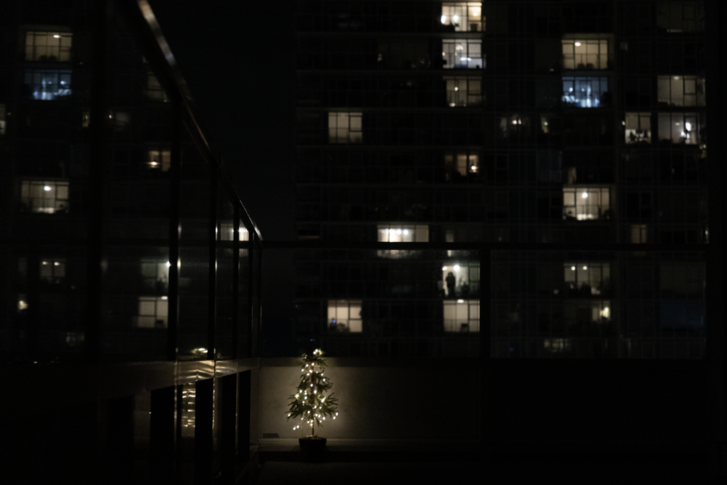
I took a baseline shot of a small Christmas tree placed 8 meters from the camera, with focus set on the Christmas tree, to use as a reference for ZDefocus. The focal lengths were 24 mm and 70 mm, respectively. Additionally, I also took defocused shots with the focal plane set at 0.5 m, 1 m, and 2 m to use for comparison.
focal distance: 500 mm、1000 mm、 2000 mm
object distance: 8000 mm
f stop: 2.8
sensor size: 35.9×24 mm
resolution: 6016×4016 px
The second set of tests was using Sony A73 with a FE 28-70 mm f/5.6 lens.
focal distance: 500 mm、1000 mm、 2000 mm
object distance: 8000 mm
f stop: 5.6
sensor size: 35.6×23.8 mm
resolution: 6000×4000 px
The information pertains to the camera and on-site records, where the object distance in compositing applications is the depth channel provided by the CG department. By filling this information into the formula, we can compute the results.

- with object at infinite distance

In other words, when using Nikon 750D, if the focal plane is at a distance of 1 m, an object at 8 m away should have a blur disk with a radius of 137.575 pixels, while an object at infinity should have a blur disk with a radius of 157.228 pixels.
Note that the blur disk at infinity is not necessarily the maximum value; objects closer to the camera may have larger blur disk.
If the lens model is known, you can check the manufacturer’s website. Detailed specifications usually list the minimum focusing distance, which you can use in the formula to calculate the maximum blur circle radius.
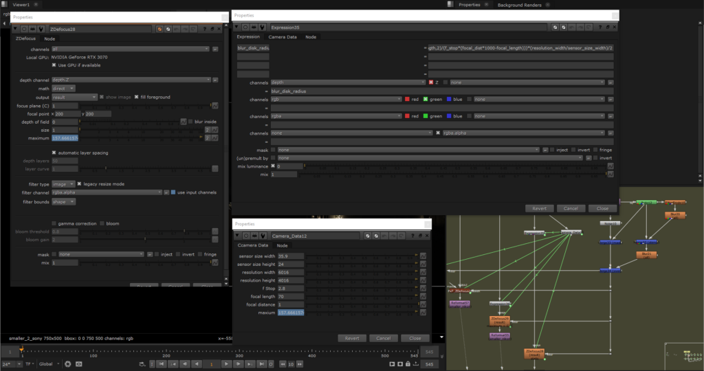
The image above shows the settings for ZDefocus. Remember how to drive the depth we mentioned earlier? If you’ve forgotten, you can click this to review.
The steps are:
- Use expressions to calculate the formula and replace the old depth channel.
- Set
mathtodirectandsizeto 1 (according to the definition). - Calculate the maximum value of the blur disk diameter for infinity.
In the comparison image, the left side shows the original Nikon capture, while the right side shows the ZDefocus result. The defocused areas have been slightly highlighted for easier identification.


Sony on the left hand side, ZDefocus on the right.


Ideally, the size in ZDefocus should be set using the formula at infinity, but in practice, using the non-infinite formula results in a size that’s closer to what’s observed.
After calculating this baseline value as starting point, if further adjustments are needed, it’s usually best to start with the “focal distance.” The camera’s aperture and focal length are generally fixed, while the focus distance is based on the data provided by the tracking department, often set to 5 m or 5.99 m, which can have significant error compare to actual value on set. Therefore, if adjustments are necessary, it is recommended to focus on this parameter.
Although the values from the formula may not be perfectly identical to those captured by the camera, they are sufficiently close to be indistinguishable without a real depth-of-field reference. Even if manual adjustments are required, we have reduced the variables to just one for adjustment.
Some aspects are challenging to replicate, such as the brightness and edge of bokehs in real photos, which often appear much brighter and sharper than in ZDefocus simulations. This is because real-world defocus still receives actual light source brightness, while ZDefocus can only expand the pixels from small points of light that its have been compressed from no defocus and lower light sources. Other effects like cat eye shapes, bokeh shapes, and brightness seen in comparison images are not in this discussion.
